There was a well-known painter in 1878 named James McNeill Whistler who was sued for the prices of a painting because it had been created in only two days. He was ordered in court to explain the cost:
“Oh, two days! The labour of two days, then, is that for which you ask two hundred guineas!”
“No;—I ask it for the knowledge of a lifetime.”
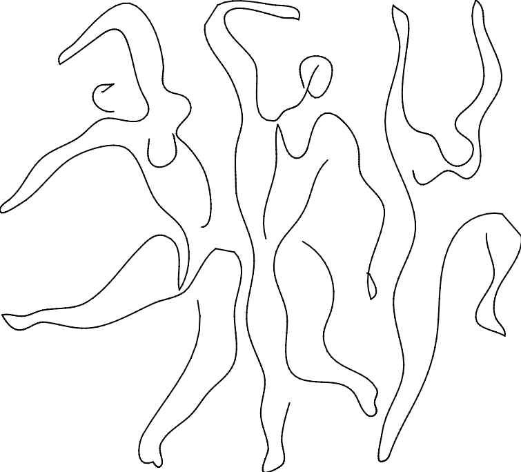
This quote about charging high prices for small artworks eventually got attributed to Picasso apocryphally. Picasso’s paintings and drawings are among the most valuable, though he has a great many drawings that are exceedingly simplistic. In fact, Picasso create a whole series of drawings using sometimes just a single-line.

These drawings are simple and beautiful. I got to thinking about reproducing them. But instead of printing them with an inkjet printer, I was interested in drawing them in the style they were meant to be created - using one line.
Converting a drawing to a one-line drawing
The drawings I am interested in reconstructing are done in one (but sometimes two or three) lines. To figure out the line, I would need to do several steps. I will be starting from a plain image - like a .png or .jpg file. The .png/.jpg is called a raster image. That is - it has information about pixels and intensities but no information about lines.
I would need a program to trace out the lines in the image and convert it to a coordinate system describing lines. This is what vector graphics are for - and there is a image format already encompassing it called scalable vector graphics (SVG).
Once I have the SVG file with the lines, I would need to gather up all the coordinates and the lines and consolidate the lines so that it creates a single seamless line.
Converting a raster image to vector graphics
I am going to start with a simple line drawing - this one-line drawing of a person.
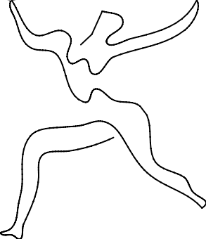
Its pretty clear to see the one line with our human eyes, the challenge here will be to get a computer to also recognize it. The first thing to do is to convert it to a SVG, and we can use two programs: imagemagick and autotrace.
First, using imagemagick’s convert command, the image is thresholded and output into a format nessecary for the next tool.
> convert person.jpg -threshold 60% person.tga
Next the resulting image person.tga can be converted using autotrace into a vector graphic file using the “centerline” algorithm that finds the skeleton center line.
> autotrace -output-file person.svg --output-format svg --centerline person.tga
Great, now we have an SVG file (person.svg) to work with for the next step.
Parsing SVG and consolidating lines
Parsing a SVG is standard thing to do and easy to do with lots of tools. The actual SVG content contains a list of coordinates in “paths” which are denoted by “line commands”. Some of the coordinates are Bezier curves definitions which themselves need to be converted to absolute coordinates.
Also an SVG that looks like it contains only one line may not in fact contain one line. For example, part of the person.svg path looks like:
There are special letters (like “M”) denoted where the path should move before starting the next stroke. The presence of these moves means that the SVG I have is actually multiple lines and not a single line.
I need to join these lines together, but first I need to re-order them in the correct order. To re-order the lines I wrote a simple algorithm that uses gradient descent to minimize the distances between subsequent end and start points of each line. This randomly looks through all possible combinations of lines until it finds the best one (though its not guaranteed to be the best).
Once I have that I can output a little animation showing the way the line moves by following the coordinates of my freshly ordered lines:
Now that I have coordinates I can get to the drawing.
Now for the actual drawing
This year my goal is to learn CAD design and to facilitate that I invested in a 3D printer. Of course 3D printers use plastic to make 3D things, but ironically one of my first 3D prints was to make a pen holder so I could make 2D things - I printed out a compatible pen holder (Thingiverse thing:4764350 designed by Pete Manville).
Now to convert the SVG to Gcode. Gcode essentially produces an instruction to move in the X/Y/Z axis. Using special instructions ("G90" and “G91”) you can also switch between absolute/relative coordinate systems. can communicate in absolute and relative coordinates. I can just parse my SVG coordinates, and for each new line it will switch to relative coordinates, move the pen up (in the Z-axis), switch to absolute coordinates, move to the new line start, switch to relative coordinates, then move back down, and finally switch to absolute coordinates and go ahead and draw. It looks something like this:
G91 ; Set coordinates to relative
G1 Z10 F1000 ; raise pen
G90 ; Set coordinates to absolute
G1 X42.712 Y51.772 F1000
G91 ; Set coordinates to relative
G1 Z0 F1000 ; lower pen
G90 ; Set coordinates to absolute
G1 X41.137 Y52.487 F1000
Since 3D/CNC machines talk to computers over Serial, its simple enough for my program to simply upload the Gcode after converting the file so that it can draw.
And that’s it!
As a bonus I can use this same code to draw my own SVG’s and upload them to print really easily with this workflow.
Source code
The source code for everything in this post can be found on my Github: schollz/svg2gcode. The basic workflow is as follows:
> # imagemagick to threshold image
> convert IMAGE -resize 300x -background White -gravity center -threshold 60% 1.tga
> # autotrace to get center line
> autotrace -output-file potrace.svg --output-format svg --centerline 1.tga
> # convert to Gcode
> svg2gcode convert --debug --png --in potrace.svg --out IMAGE -x 0 -y 0 --width 90 --height 90 --simplify 0.005 --consolidate 0.07 --min-length 0.03 --animate
> # upload to printer
> svg2gcode upload IMAGE.gcode